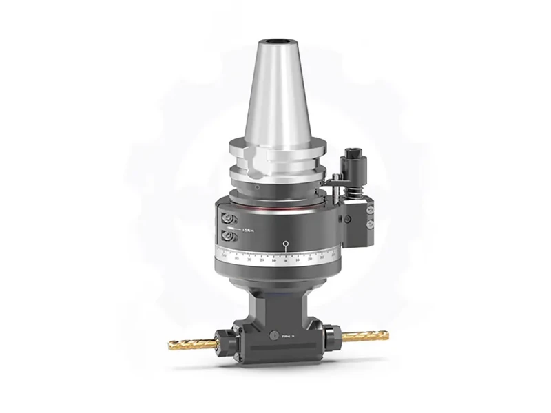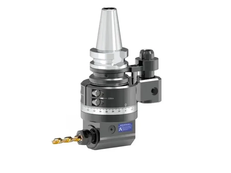
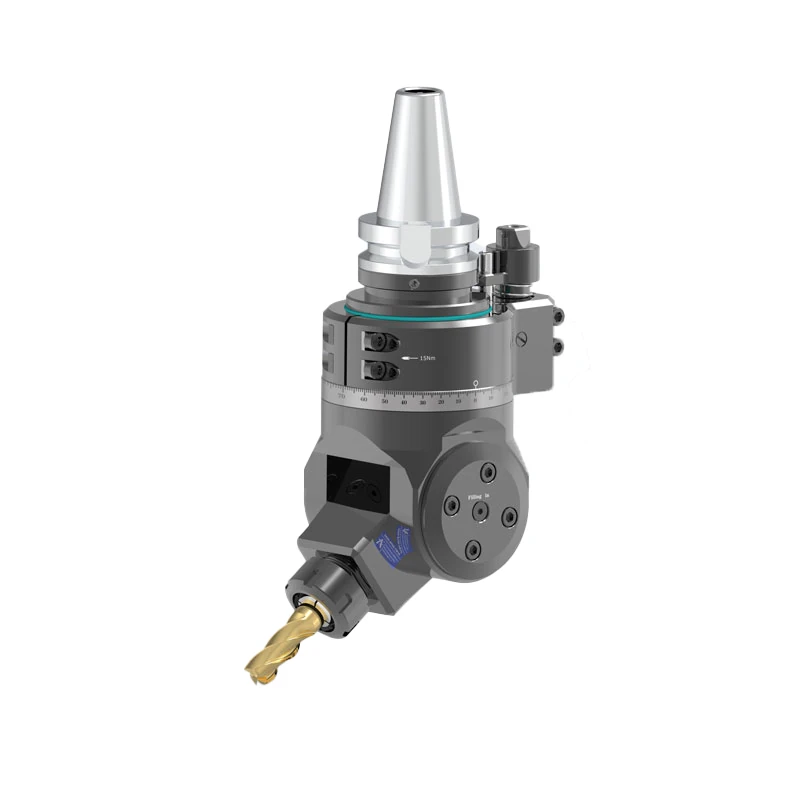
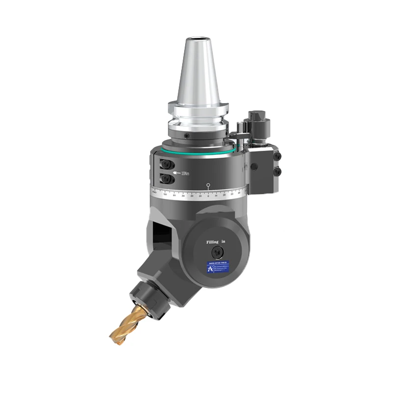
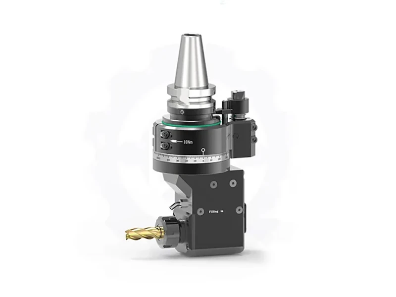

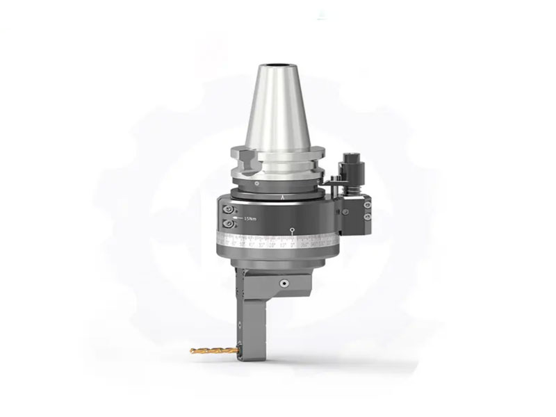
In CNC machining, an angle head allows a cutting tool to approach a workpiece from a different direction. It is commonly used for side milling, drilling, tapping, and thread milling when the machine spindle cannot reach the feature directly.
The main difference between slim and standard angle heads is their suitability for different machining spaces. A standard design works well when there is sufficient clearance around the workpiece, while a slim design is intended for restricted areas such as narrow cavities, deep channels, and features close to high side walls.
For manufacturers and machining professionals, choosing between the two requires more than checking whether the head provides 90° output. Workpiece geometry, required reach, tool size, spindle speed, torque, and machine compatibility all need to be considered.
Key Takeaways
- Slim angle heads are designed for restricted machining areas, where a conventional head may interfere with the workpiece.
- Standard angle heads are suitable for more open machining areas where head size is less of a concern.
- The right choice depends on clearance, reach, tool size, torque, speed, and spindle interface.
- A compact design does not automatically mean better performance. The angle head still needs to match the actual cutting conditions.
- Before purchasing, check the workpiece geometry and CNC machine specifications to avoid interference or compatibility issues.
What Is a CNC Angle Head?
A CNC angle head is a machining attachment that changes the direction of the cutting tool. By mounting an angle head on a machining center, manufacturers can perform operations on side surfaces or internal features without necessarily repositioning the workpiece.
A fixed 90 degree angle head provides an output direction at 90° to the machine spindle. This configuration is commonly used when a feature needs to be machined from the side rather than along the spindle axis.
For B2B applications, the output angle is only one part of the selection process. The physical dimensions of the head, reach, tool clamping system, rated speed, torque, and spindle interface should also be matched to the machining task.
Slim vs. Standard Angle Heads: What Is the Difference?
The primary difference is the amount of machining clearance each design requires.
A standard angle head is generally suitable when the area around the machining feature is relatively open. If there is enough room for the head body and cutting tool, a conventional configuration can handle many common side-machining operations.
A slim angle head is designed for more restricted environments. Its compact structure can make it easier to position the cutting tool inside narrow cavities or around obstacles that would interfere with a larger head.
The decision should therefore be based on the actual geometry of the workpiece rather than simply choosing the smallest available head.
Size and Cutter Clearance
For a small right angle milling head, external dimensions directly affect tool accessibility.
When machining inside a narrow cavity, the angle head body must pass through the available opening without contacting the workpiece. A more compact design can provide additional clearance around the cutting position.
However, head size should not be considered in isolation. Tool diameter, clamping method, required torque, and overall rigidity still need to meet the requirements of the application.
Reach and Machining Accessibility
Reach is another important consideration when the machining feature is located deep inside a workpiece.
A head that is too short may not reach the required position, while an unnecessarily long configuration may not be appropriate for the machining setup. The required gage length should be determined from the distance between the machine spindle and the feature being machined.
For this reason, both head diameter and reach should be checked before selecting an angle head.
Cutting Capacity and Rigidity
Space is an important consideration for slim designs, but cutting performance remains equally relevant.
The required torque depends on factors such as the cutting tool, workpiece material, cutting conditions, and machining operation. The selected angle head should have sufficient rigidity and torque for the intended application.
For heavier side milling, buyers should pay particular attention to the relationship between tool diameter, cutting load, spindle speed, and head rigidity.
When Should You Choose a Slim Right Angle Head?
A slim right angle head is worth considering when access to the machining feature is the main challenge.
Narrow Cavities and Deep Internal Features
Deep cavities, narrow channels, and high side walls can restrict the movement of a conventional angle head. Even if the cutting tool itself is small enough, the body of the angle head may still interfere with the workpiece.
A slim design can reduce this type of interference and provide better access to internal features.
This configuration can be particularly useful for complex components with limited internal machining space, including automotive parts and molds.
Side Milling and Thread Processing
A 90 degree angle head allows the cutting tool to approach a side feature horizontally while the workpiece remains mounted on the machining center.
Depending on the configuration and tooling, angle heads can be used for side milling, internal slotting, tapping, and thread milling.
Keeping the workpiece in the same setup can also help avoid errors associated with repeated repositioning, which can be important when several features need to maintain a specific positional relationship.
When Is a Standard Right Angle Head a Better Choice?
A standard right angle head can be a practical choice when the machining area is open and there is sufficient clearance around the workpiece.
In this situation, the compact dimensions of a slim design may not provide a meaningful advantage. Buyers can instead focus on factors such as cutting capacity, tool diameter, torque, speed, rigidity, and the requirements of the machining process.
There is also no need to select a slim model simply because it has a smaller profile. If space is not a limitation, the overall machining requirements should determine the configuration.
How to Choose the Right Angle Head for Your CNC Machine?
A practical selection process starts with the workpiece and machining operation.
Check the Available Machining Space
Measure the width and depth of the machining area and identify any walls, cavities, fixtures, or other structures that could interfere with the angle head.
The complete setup should be checked, including both the angle head and cutting tool. This helps determine whether a slim configuration is necessary or whether a standard design provides enough clearance.
Match the Reach to the Machining Feature
Determine how far the cutting tool needs to extend from the machine spindle to reach the feature.
The selected gage length should be sufficient for the application without being unnecessarily long. This is particularly important when machining deep internal features.
Consider Tool Size, Speed, and Torque
The cutting tool, workpiece material, cutting conditions, and required machining operation should all be considered together.
The angle head must provide a suitable clamping range and sufficient torque for the selected tool. Maximum speed is equally important.
The machine spindle must not be operated above the rated maximum speed of the angle head. Excessive speed can increase friction and heat inside the gears and bearings, accelerate wear, and in severe cases cause gear damage or seizure. It can also affect machining accuracy.
Confirm Machine Spindle Compatibility
The spindle interface must be confirmed before ordering.
Different machining centers use different spindle standards, so the angle head needs to match the actual machine configuration. Providing the machine model and spindle specification to the supplier is a practical way to confirm compatibility before purchase.
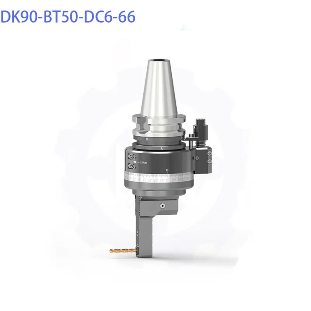
Slim 90° Right Angle Head: DK90-BT50 DC Collet Series
For applications where conventional angle heads have difficulty entering restricted areas, the Slim 90° Right Angle Head (DK90-BT50 DC Collet Series) is designed for narrow-cavity side milling, internal slotting, and deep bore thread processing.
The series is designed for BT50 vertical machining centers (VMC) and horizontal machining centers (HMC). Its internal pull-back DC double-chuck collet mechanism eliminates the need for a wide external collet nut.
This structure reduces the front cutter swing diameter to D35 mm for the DC6 model and D40 mm for the DC5M model, providing clearance for machining inside narrow, deep-wall cavities.
The series uses a heavy-wall housing and precision-ground bevel gears. Depending on the model, maximum torque ranges from 5.6 Nm to 46.0 Nm, while maximum speed ranges from 4,500 to 6,000 RPM.
Key Technical Features
- DC pull-back collet system: The internal clamping mechanism eliminates the wide external collet nut and helps reduce the front swing diameter.
- High-rigidity housing: The housing is designed to absorb cutting vibration during extended gage length operations.
- Precision-ground bevel gears: The gears are made from 20CrMnTi alloy steel and treated to a hardness of HRC 58–62.
- Preloaded P4-class bearings: Precision angular contact ball bearings are used to handle axial thrust and radial cutting loads.
DK90-BT50 DC Series Technical Specifications
| Model | Input Shank | Spindle Output | Gage Length | Max. Speed | Passing Dia. | Clamping Range | Tapping Capacity | Max. Torque | Net Weight |
| DK90-BT50-DC5M-50 | BT50 | DC5M | 50 mm | 6,000 RPM | D40 mm | Ø1–Ø5 mm | M3–M4 | 5.6 Nm | 11.200 kg |
| DK90-BT50-DC6-66 | BT50 | DC6 | 66 mm | 6,000 RPM | D35 mm | Ø1–Ø6 mm | Thread Milling | 10.8 Nm | 11.450 kg |
| DK90-BT50-DC7-52 | BT50 | DC7 | 52 mm | 6,000 RPM | D50 mm | Ø1–Ø7 mm | Thread Milling | 10.8 Nm | 11.800 kg |
| DK90-BT50-DC7-120 | BT50 | DC7 | 120 mm | 6,000 RPM | D50 mm | Ø1–Ø7 mm | Thread Milling | 10.8 Nm | 12.300 kg |
| DK90-BT50-DC8-160 | BT50 | DC8 | 160 mm | 6,000 RPM | D45 mm | Ø4–Ø10 mm | M5–M10 | 23.0 Nm | 13.500 kg |
| DK90-BT50-DC10 | BT50 | DC10 | 140.5 mm | 6,000 RPM | D51 mm | Ø4–Ø10 mm | M5–M10 | 23.0 Nm | 13.800 kg |
| DK90-BT50-DC13 | BT50 | DC13 | 100 mm | 5,000 RPM | D70 mm | Ø3–Ø13 mm | M6–M12 | 35.0 Nm | 15.200 kg |
| DK90-BT50-DC16-65 | BT50 | DC16 | 65 mm | 4,500 RPM | D85 mm | Ø3–Ø16 mm | M6–M14 | 46.0 Nm | 15.800 kg |
| DK90-BT50-DC16-99 | BT50 | DC16 | 99 mm | 4,500 RPM | D85 mm | Ø3–Ø16 mm | M6–M14 | 46.0 Nm | 16.500 kg |
| DK90-BT50-DC16-145 | BT50 | DC16 | 145 mm | 4,500 RPM | D85 mm | Ø3–Ø16 mm | M6–M14 | 46.0 Nm | 17.307 kg |
| DK90-BT50-DC16-185 | BT50 | DC16 | 185 mm | 4,500 RPM | D85 mm | Ø3–Ø16 mm | M6–M14 | 46.0 Nm | 18.200 kg |
The bevel gears are made from 20CrMnTi alloy steel and undergo gas carburizing, quenching, and precision grinding. The gear hardness is HRC 58–62, with ISO Grade 4 grinding precision. The stated transmission backlash is ≤15 arcmin, while running noise is ≤70 dB under full operational load.
The series also uses preloaded P4-class angular contact ball bearings. According to the supplied product information, NSK/FAG bearings are used to handle axial thrust and radial cutting loads.
Automotive Transmission Housing Machining Case
An automotive aluminum alloy transmission housing provides a practical example of the machining challenges that can occur in a restricted internal space.
The housing contains narrow cavities, side walls, and multiple lateral threaded mounting holes. With the previous process, limited access required repeated workpiece repositioning and fixturing. This could lead to positioning deviations as well as thread defects such as damaged threads and burrs, making it difficult to maintain the required production rhythm.
In this application, a Slim angle head was installed on a vertical machining center. Its narrow body could enter the restricted cavity and complete side-hole machining, tapping, and thread milling in a single setup.
The thread position was controlled within ±0.02 mm, with complete thread profiles. Compared with the previous process, fewer workpiece reorientations and fixtures were required. The machining cycle per part was shortened, and the thread defect rate was significantly reduced, making the setup suitable for high-volume automated transmission housing production.
Quality, Installation, and Operating Considerations
The product is manufactured under an ISO 9001:2015 quality management system. According to the supplied information, each DK90-BT50 DC series unit undergoes inspection before shipment.
The inspection process includes spindle taper and DC collet cone runout testing, a 60-minute continuous run-in test at the full rated operating speed, and anti-backlash calibration.
For installation, the stop block should be securely mounted to the machine spindle face. The center-to-center distance between the machine spindle and positioning pin socket should be checked against the ordered G-dimension.
After installation, side runout should be checked with a ground test arbor. An ATC test at low speed should also be carried out to confirm that the BT50 taper can be picked up, seated, and released without interference.
During operation, the angle head must remain within its rated speed. Operating above the specified limit can cause excessive heat and friction in the internal gears and bearings, leading to accelerated wear, gear damage, seizure, or reduced machining accuracy.
For a CW-CW configuration, the angle head rotates in the same direction as the machine spindle. When the spindle rotates forward, the angle head rotates forward; when the spindle reverses, the angle head also reverses.
Frequently Asked Questions About CNC Angle Heads
Can a Slim Angle Head Fit My CNC Machine?
Compatibility depends on the machine spindle interface and the required configuration. The DK90-BT50 DC series is designed for BT50 applications. For other spindle standards or special machine configurations, the machine spindle specification should be provided before purchasing.
What Is the Difference Between Tapping Capacity and Drilling Diameter?
They refer to different machining dimensions. Drilling diameter is the size of the hole made before threading, while tapping capacity refers to the thread specification that can be machined.
For example, an M8 thread requires an appropriate smaller pre-drilled hole before tapping rather than an 8 mm hole.
Can a 90 Degree Angle Head Run at the Same Speed as the CNC Spindle?
Only when the CNC spindle speed remains within the rated maximum speed of the angle head. The specified speed limit of the angle head must always be followed during operation.
How Does the Angle Head Rotate When the CNC Spindle Reverses?
For a CW-CW configuration, the angle head follows the rotation direction of the CNC spindle. Forward spindle rotation produces forward angle-head rotation, while reverse spindle rotation produces reverse angle-head rotation.
Conclusion
The choice between a slim and standard angle head comes down primarily to the relationship between workpiece geometry and machining requirements.
A standard design is suitable when there is enough clearance around the machining area. A slim design becomes more useful when deep cavities, narrow channels, or internal side features make access difficult.
For buyers evaluating an angle head, the key is to first identify the actual machining constraints and then match the head dimensions, reach, tooling, speed, torque, and spindle interface to those requirements. The DK90-BT50 DC series provides multiple configurations for applications where restricted access is a major consideration. If you are unsure which configuration fits your CNC machine and machining requirements, contact our technical team for model selection and application support.
Related Articles
You May Also Like