
What Is a BT40 Right Angle Head?
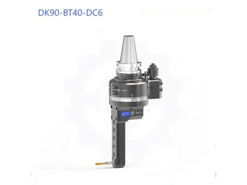
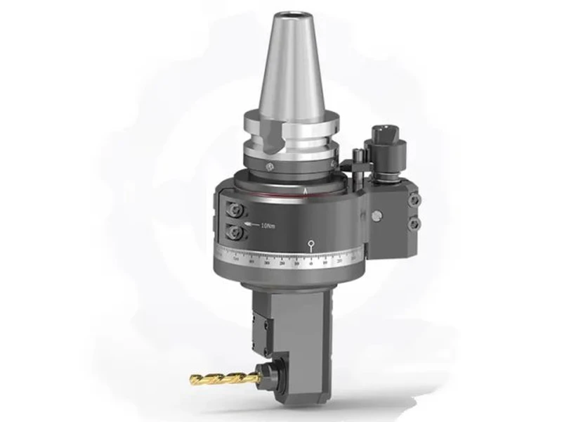
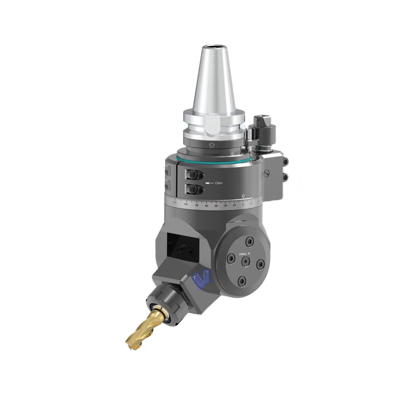
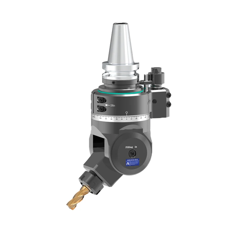
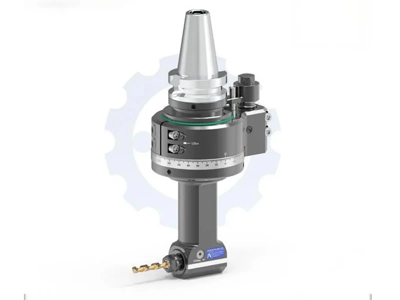
A BT40 right angle head is a machine tool attachment that changes the cutting direction of a CNC machine spindle by 90 degrees. It allows cutting tools to approach the workpiece from the side, making it possible to machine certain features without repositioning the workpiece.
This is particularly useful for components with side slots, lateral mounting faces, internal surfaces, and holes that are difficult to reach with a conventional vertical spindle. By completing multiple machining operations in one setup, manufacturers can reduce workpiece repositioning and help maintain consistent machining positions.
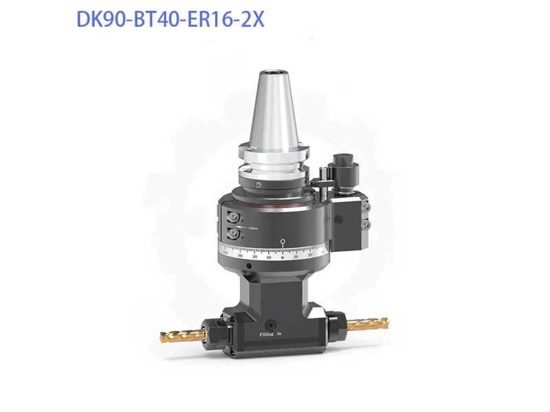
The DK90-BT40 ER Series is a standard 90-degree attachment designed for medium-to-heavy side milling, drilling, and tapping on BT40 vertical machining centers (VMCs). It features a BT40 input shank and an ER collet output spindle, with several output sizes and projection lengths available for different machining requirements.
How a 90 Degree Angle Head Works on a CNC Machine
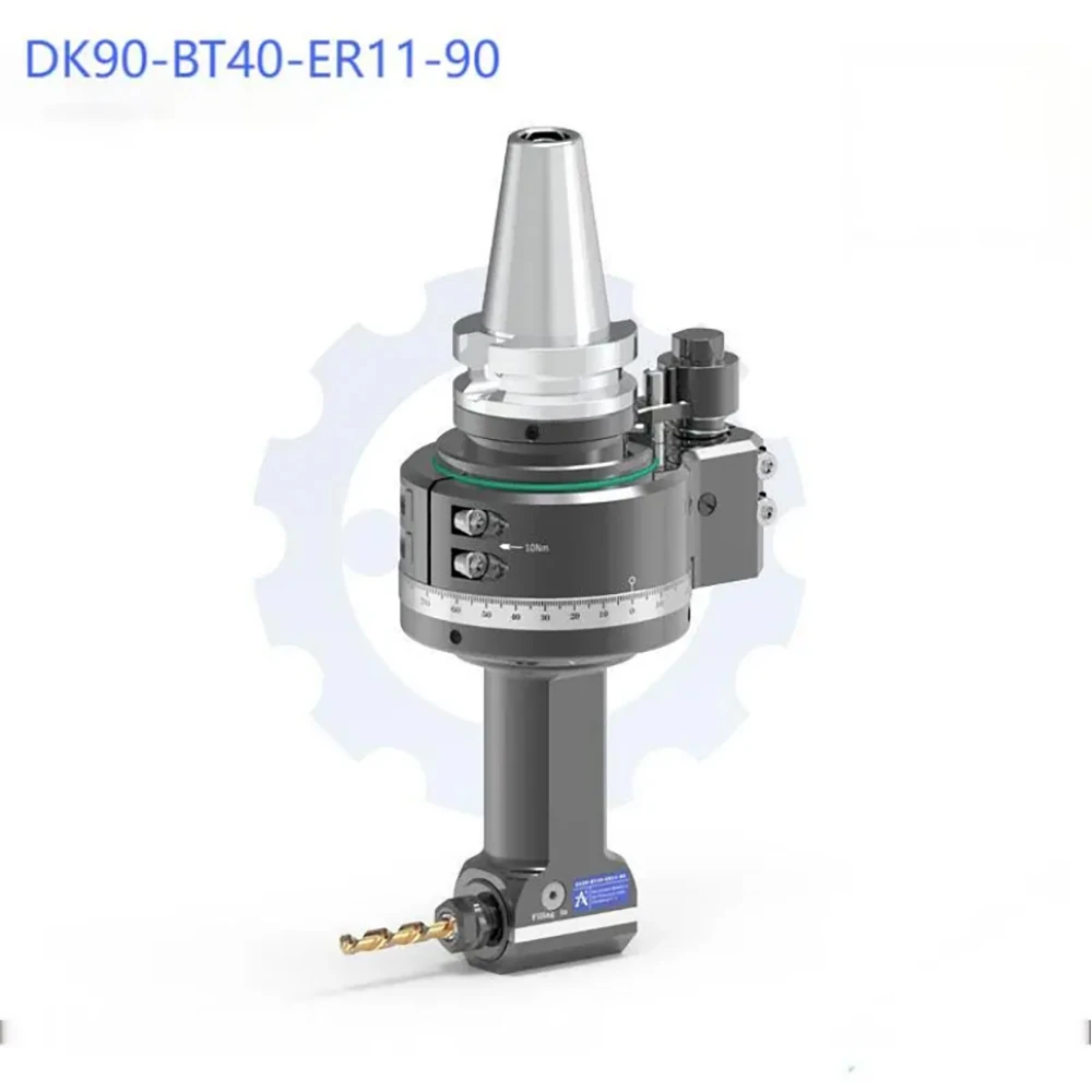
A 90 degree angle head transfers spindle rotation through an internal gear mechanism to an output spindle positioned perpendicular to the machine spindle. The cutting tool can then approach the workpiece horizontally or from another suitable side direction, depending on the machine setup and workpiece orientation.
The DK90-BT40 ER Series uses spiral bevel gears for power transmission and supports a 1:1 gear ratio across the listed models. This means the input and output rotational speeds have a nominal one-to-one relationship, subject to the machine’s operating conditions and the attachment’s rated speed.
Benefits of Side Machining in a Single Setup
Side machining can simplify production when a component has features on multiple faces. Instead of removing the workpiece and securing it in a different position, an angle head may allow additional operations to be completed in the original setup.
This can help reduce repositioning errors and shorten handling time. It is especially relevant to components with lateral holes, side slots, or recessed features. The actual benefit depends on the workpiece geometry, fixture design, tool access, and machining process.
What Can a CNC Angle Head Do?
A CNC angle head expands the range of cutting directions available on a compatible machine. The DK90-BT40 ER Series is designed for side milling, drilling, and tapping, covering several common operations in industrial component manufacturing.
Side Milling for Flats, Slots, and Pockets
Side milling is useful for machining flat surfaces, grooves, slots, and other features that are not conveniently accessible from the top of a workpiece. A right angle head positions the cutting tool to approach these features from the side.
For automotive housings and die or mold components, this arrangement can help machine lateral mounting faces, side walls, and slider tracks. Tool selection, cutting parameters, and the available clearance should be evaluated according to the material and the required surface finish.
Drilling Holes on Vertical and Side Faces
Some components require holes on vertical faces or in areas where a conventional vertical spindle cannot approach the workpiece directly. A 90-degree attachment can redirect the cutting tool toward these locations.
This is useful for selected cross-holes, lateral mounting holes, and angled-access machining tasks, provided the required tool path and clearance are available. The DK90-BT40 ER Series supports different ER collet sizes and projection lengths, allowing users to select a configuration based on the required tool diameter and access conditions.
Tapping Threads in Hard-to-Reach Areas
Tapping creates internal threads for bolts, fasteners, and other threaded connections. When a threaded hole is located on a side face or inside a restricted area, an angle head can provide a more suitable tool approach.
The DK90-BT40 ER Series has listed tapping capacities ranging from M5–M6 for ER11 models to M6–M16 for the ER32 model. These figures indicate the stated capacity ranges for the respective configurations; actual tapping suitability depends on the workpiece material, thread requirements, tool selection, and machining conditions.
How to Choose the Right BT40 Angle Head
Selecting an angle head involves more than matching the machine’s spindle interface. Buyers should also consider cutting tool diameter, required reach, rotational speed, torque, and available clearance.
Selecting the Right ER Collet Size
The ER collet system determines the supported tool clamping range. In the DK90-BT40 ER Series, four output configurations are available.
| ER Collet | Clamping Range | Maximum Speed | Maximum Torque |
| ER11 | Ø1–7 mm | 8,000 RPM | 10.8 Nm* |
| ER16 | Ø1–10 mm | 8,000 RPM | 18 Nm |
| ER25 | Ø1–16 mm | 6,800 RPM | 46 Nm |
| ER32 | Ø1–20 mm | 5,000 RPM | 65 Nm |
The ER11 maximum torque varies by model: 10.8 Nm for the 90 mm model and 8.8 Nm for the 140 mm and 190 mm models.
Smaller ER sizes accommodate smaller-diameter tools, while ER25 and ER32 offer larger clamping ranges and higher listed torque capacities. However, a larger collet is not automatically the better choice. The configuration should match the cutting tool, machining load, and required operating speed.
Choosing the Appropriate Gage Length
Gage length affects how far the output spindle projects and whether the cutting tool can reach the target feature. A shorter configuration may suit accessible side features, while a longer projection may be needed for recessed areas or restricted access.
The DK90-BT40 ER Series offers different lengths according to the ER configuration:
- ER11: 90 mm, 140 mm, and 190 mm.
- ER16: 66 mm, 110 mm, 160 mm, 210 mm, and 260 mm.
- ER25: 66 mm, 110 mm, 160 mm, and 210 mm.
- ER32: 80 mm.
Longer reach can improve access but may also affect tool clearance and machining stability. Buyers should check the complete assembly dimensions and workpiece geometry before choosing a model.
Matching Spindle Speed and Torque to Machining Requirements
Maximum speed and torque are important when selecting an attachment for a particular operation. The listed maximum speed decreases from 8,000 RPM for ER11 and ER16 models to 6,800 RPM for ER25 and 5,000 RPM for ER32. Maximum torque increases across these configurations, reaching 65 Nm on the listed ER32 model.
These ratings provide a starting point for selection, but they do not replace process planning. The required cutting speed, feed rate, tool diameter, workpiece material, and cutting load should all be considered before setting machining parameters.
DK90-BT40 ER Series: Technical Specifications and Features
The DK90-BT40 ER Series combines a BT40 input shank with multiple ER output options. Its design focuses on structural rigidity, gear transmission, spindle support, and configuration flexibility for industrial machining applications.
ER11, ER16, ER25, and ER32 Configurations
The series includes 14 listed models with projection lengths suited to different access requirements. All listed models have a 1:1 gear ratio and a maximum rated speed of either 8,000, 6,800, or 5,000 RPM, depending on the configuration.
The stated tapping capacity ranges from M5–M6 on ER11 models to M6–M16 on the ER32 model. The maximum passing diameter also varies by configuration, from D75 mm for ER11 to D155 mm for ER32.
All models listed in our specification table are marked as in stock. Please contact us to confirm the availability of your selected model and configuration before placing an order.
Gear Transmission and Spindle Bearing Design
The drive system uses OKAMOTO ground spiral bevel gears made from 20CrMnTi alloy steel. According to the supplied technical information, the gears undergo carburizing, quenching, and grinding to ISO Grade 4 precision. The stated transmission backlash is no more than 15 arcminutes, with running noise specified at no more than 70 dB under maximum RPM.
The output spindle is supported by preloaded angular contact ball bearings from NSK or FAG, specified as P4 grade. This bearing arrangement is intended to support combined radial cutting forces and axial thrust during machining.
Housing Material and Structural Rigidity
The housing uses QT500-7 ductile cast iron. The monoblock casting undergoes artificial aging and stress-relief heat treatment to improve damping and torsional rigidity while minimizing thermal expansion under load.
These construction details are relevant when evaluating an attachment for medium-to-heavy machining. In practice, overall performance also depends on correct installation, tool balance, machine condition, workholding, and cutting parameters.
Frequently Asked Questions About BT40 Angle Heads
Can a BT40 Angle Head Perform Both Milling and Drilling?
Yes. The DK90-BT40 ER Series is designed for side milling, drilling, and tapping. The appropriate model depends on the cutting tool diameter, required reach, operating speed, and machining load.
What Is the Difference Between ER Collet Sizes?
ER collet sizes determine the supported tool clamping range. In this series, ER11 supports Ø1–7 mm tools, ER16 supports Ø1–10 mm, ER25 supports Ø1–16 mm, and ER32 supports Ø1–20 mm. Their listed maximum speeds and torque capacities also differ.
How Do You Choose the Gage Length of a Right Angle Head?
Choose a length that provides sufficient access to the target feature while maintaining appropriate clearance from the workpiece, fixture, and machine components. Check the actual assembly dimensions and tool path before finalizing the configuration.
Conclusion
A BT40 right angle head can extend the machining capabilities of a compatible CNC machine by providing access to side faces, slots, holes, and threaded features that are difficult to reach with a conventional vertical spindle. Selecting the right configuration requires attention to ER collet size, gage length, maximum speed, torque, and machine compatibility.
The DK90-BT40 ER Series offers ER11, ER16, ER25, and ER32 output options, with multiple projection lengths and stated technical specifications for different machining requirements. For B2B buyers, comparing these parameters with actual workpiece dimensions and machining processes is a practical starting point for choosing a suitable model.
Contact our team with your required ER size, gage length, machining application, and machine interface to discuss the appropriate DK90-BT40 ER Series configuration and request a quotation.
Related Articles
You May Also Like