
Why Are Narrow Cavities Difficult to Machine?
Narrow cavities are common in mold components, hydraulic valve blocks, and automotive parts. These features may include internal slots, side holes, keyways, and threaded holes located inside a workpiece. Although the dimensions of these features may be relatively small, machining them can be more complicated than working on an open surface.
The main challenge is tool access. A standard milling cutter or drill approaches the workpiece along the spindle axis. When a hole or slot is located on an internal sidewall, the machine spindle may not be able to position the cutting tool at the required angle. Even when the tool can reach the feature, the surrounding walls may leave insufficient clearance for the tool holder or spindle nose.
Tool reach is another consideration. A longer tool can extend farther into a cavity, but excessive overhang may increase vibration and reduce machining stability. This can affect surface finish, dimensional accuracy, and tool life.
For manufacturers, the solution is not always to use a larger machine or redesign the entire machining process. The first step is to determine whether the required cutting direction can be achieved with the existing machine setup.
Common Methods for Machining Internal Side Features
Several approaches can be used to machine features inside narrow cavities. The appropriate method depends on cavity dimensions, feature geometry, cutting requirements, and the available machine tools.
1. Using Extended Cutting Tools
Long-reach cutters can access features located deep inside a workpiece. This approach may be suitable when the tool can follow the required machining direction and sufficient clearance is available.
However, increasing tool length also increases overhang. Under cutting loads, a long tool may deflect or vibrate, particularly during side milling. Manufacturers must consider tool diameter, cutting conditions, workpiece material, and the rigidity of the setup.
Extended tools are therefore not always the best choice for internal side features, especially when the machining direction is difficult to achieve with a conventional spindle.
2. Repositioning the Workpiece
Another option is to rotate or reposition the workpiece so that the target feature faces the spindle. This can make the feature easier to reach without changing the cutting direction.
The disadvantage is that additional setups may be required. Each repositioning step takes time and may introduce positioning errors. For components with several internal features, repeated clamping can increase production time and make consistent accuracy more difficult to maintain.
3. Using Multi-Axis Machining
A five-axis machining center can approach features from different directions by changing the relative orientation of the tool and workpiece. This provides flexibility for complex geometries and parts that require several machining angles.
However, purchasing or allocating a five-axis machine may not be practical for every production line. Manufacturers need to consider equipment investment, programming requirements, machine availability, and the actual complexity of the part.
For some operations, a suitable attachment on an existing vertical machining center may provide a more practical alternative.
4. Using a 90 Degree Angle Head
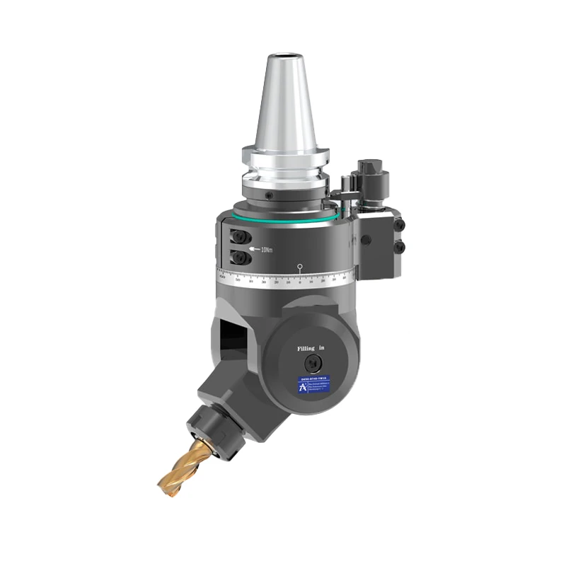
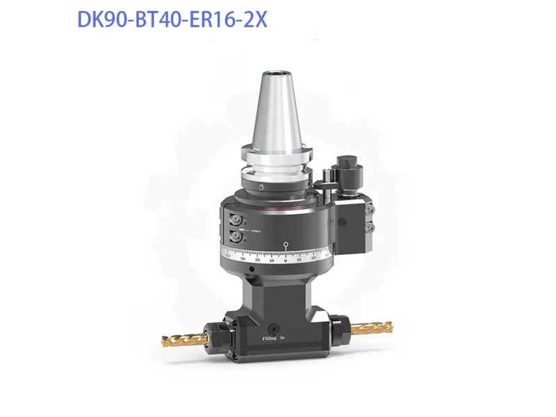
A 90 degree angle head redirects spindle output so that the cutting tool can work perpendicular to the main spindle axis. This makes it possible to machine certain side-facing features without turning the entire workpiece or changing to a different machine configuration.
The main consideration is clearance. A conventional angle head may have a housing or collet nut that is too wide to enter a narrow opening. Even if the cutting tool itself fits, the head body may collide with the cavity wall.
For this reason, selecting an angle head involves more than checking its cutting angle. The head’s external dimensions, cutter clearance, torque capacity, and compatibility with the machine must also be evaluated.
What to Consider When Choosing a Slim Right Angle Head
A slim right angle head is designed for machining operations where space around the cutting area is limited. Before selecting one, manufacturers should assess several practical factors.
Cutter Nose Diameter and Clearance
The maximum external diameter near the cutter nose is a critical dimension when machining deep or narrow cavities. A smaller diameter can provide more clearance between the head and the surrounding walls.
However, the required clearance should be checked against the actual cavity geometry, including the opening, internal depth, sidewall position, and tool approach path. A head that fits through the entrance may still lack enough room to complete the operation.
Cutting Torque and Structural Rigidity
Side milling, drilling, and tapping place different demands on an cnc angle head. The attachment must transmit the torque required by the operation while maintaining sufficient rigidity.
Housing construction and gear quality influence how the head handles cutting loads. Excessive vibration or mechanical play can affect machining consistency, particularly when the tool extends into a deep cavity.
Manufacturers should therefore compare torque capacity and structural design with the intended cutting operations rather than selecting an attachment based on size alone.
Spindle Accuracy and Speed
Spindle runout and rotational concentricity are important when machining small holes, slots, and other precision features. Poor concentricity can affect cutting consistency and the quality of the finished surface.
The required spindle speed also depends on the tool, material, and operation. Buyers should confirm that the attachment’s speed and accuracy specifications match the planned machining process.
Machine Compatibility and Setup
An angle head must match the machine’s spindle interface and available operating space. For a BT40 vertical machining center, checking the BT40 connection, overall head dimensions, tool length, and machine clearance helps prevent interference during setup.
The machining sequence should also be considered. If an angle head allows several internal features to be completed in one clamping, it may reduce repositioning and improve production efficiency. The actual benefit depends on the part geometry and the operations involved.
DK90-BT40 DC Series: A Slim Solution for Narrow Cavities
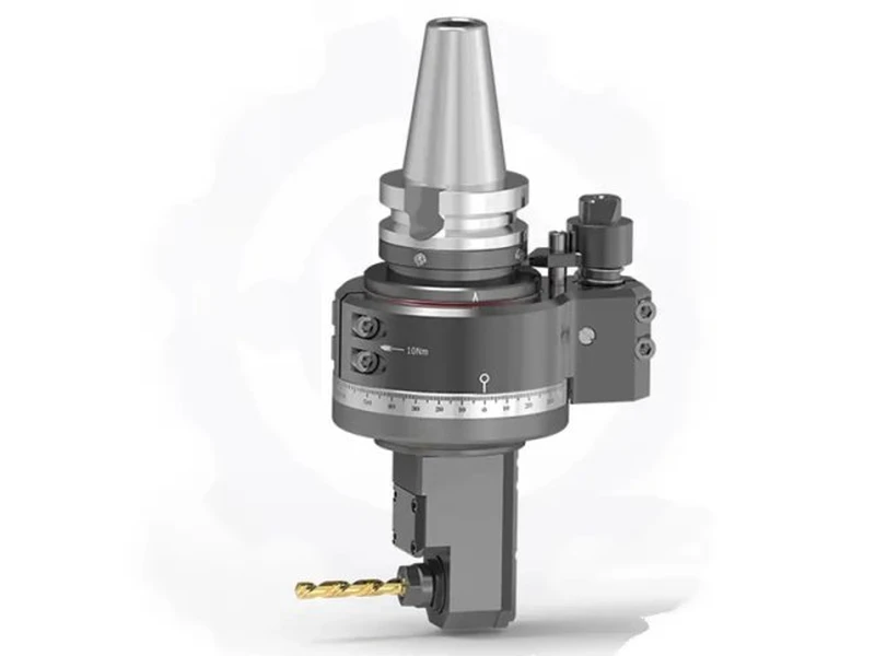
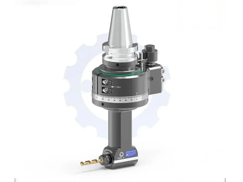
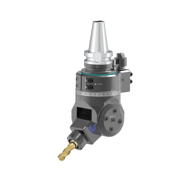
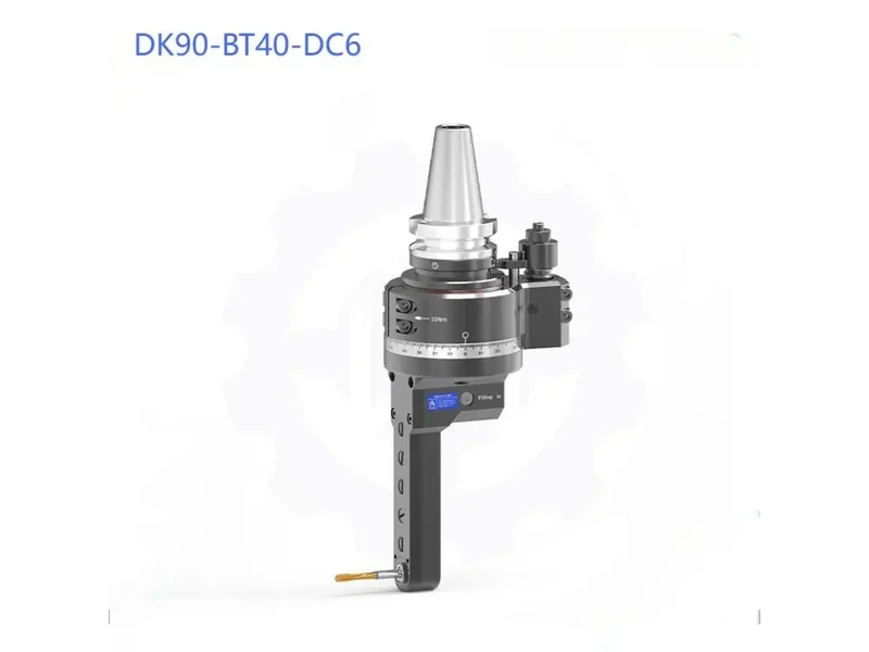
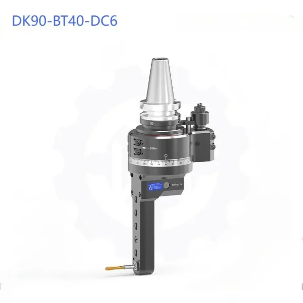
For manufacturers working with narrow internal features on BT40 vertical machining centers, our DK90-BT40 DC Series BT40 angle head offers a compact 90-degree machining solution. The series includes DC5M, DC6, DC7, DC8, and DC10 models for narrow-cavity side milling, internal slotting, and deep-bore thread processing.
Compact DC Collet Design
The DK90-BT40 DC Series uses a pull-back DC double-chuck collet mechanism. Unlike conventional external collet nuts, this internal clamping design reduces the space required around the cutter nose.
The cutter nose swing diameter is D35 mm for the DC6 configuration and D40 mm for the DC5M configuration. These compact dimensions help the angle head access narrow areas where a conventional, wider angle head may encounter interference.
Rigid Housing and Gear Transmission
The housing is made from QT500-7 material, offering high rigidity, precision, and durability. Its rigid construction supports stable machining performance in demanding applications.
The angle head uses OKAMOTO-ground spiral bevel gears made from 20CrMnTi alloy steel. The gears are gas-carburized and quenched to HRC 58–62, then ground to ISO Grade 4 precision. Transmission backlash is no more than 15 arcmin, and running noise is no more than 70 dB under full operating load.
With cutting torque of up to 23 Nm, the DK90-BT40 DC Series supports milling, drilling, and tapping operations that require reliable torque transmission.
Spindle Accuracy and Operating Speed
The DK90-BT40 DC Series uses preloaded P4-class angular contact ball bearings from NSK or FAG. Spindle nose runout is no more than 0.005 mm, and the maximum rotational speed is 6,000 RPM.
These specifications make the series suitable for evaluating precision machining applications where spindle accuracy and rotational stability are important. Actual machining results depend on machine condition, tool selection, workpiece material, setup rigidity, and cutting parameters.
Our company is certified to ISO 9001:2015, reflecting our commitment to quality management.
Application Example: Machining a Hydraulic Valve Block
Hydraulic valve blocks often contain narrow internal cavities with side holes that require drilling, milling, chamfering, or tapping. When the opening is too small for conventional tooling to enter, accessing these features from the required direction can be difficult.
In one hydraulic valve block application, the narrow internal cavity prevented conventional tools from reaching the side holes for drilling, milling, and tapping. Switching to a five-axis machining center would have increased equipment costs and complicated production arrangements.
We used our DK90 slim angle head with a vertical machining center to address this challenge. Its narrow body entered the confined cavity, while the 90-degree output enabled side machining. The head also supports 360-degree angle adjustment, allowing the cutting direction to be positioned according to the machining requirements.
With this setup, internal sidewall drilling, chamfering, and tapping were completed in a single clamping. Machining accuracy was maintained within ±0.02 mm, and the processing time per part was reduced by 40%.
Completing multiple operations in one clamping reduced the need to turn and reclamp the workpiece. This helped shorten machining time and maintain positional consistency between features.
These results demonstrate the benefits of using a slim angle head for this particular application. Actual accuracy and cycle-time improvements depend on component geometry, machine configuration, cutting tools, and process parameters.
Service Life and Precision in Production
For B2B buyers, the purchase price of an angle head is only one part of the evaluation. Service life, machining consistency, and maintenance requirements also affect the overall cost of using the attachment.
Compared with lower-priced angle heads, which typically have a service life of around six months, our DK90 angle head offers a service life of up to one year. In terms of precision, other comparable products typically achieve 0.02 mm, while our DK90 can achieve 0.01 mm.
These differences can help manufacturers evaluate long-term operating costs and machining requirements. Actual service life and machining accuracy depend on cutting load, operating hours, maintenance, tool selection, and working conditions.
The high-strength housing is designed to support durability in demanding temperature conditions. For applications involving significant temperature variations, we recommend confirming the operating temperature range and specific working conditions with our team before selecting the equipment.
Conclusion
A properly selected 90 degree angle head can redirect the cutting path and allow certain operations to be completed on an existing vertical machining center. For applications with restricted internal clearance, a slim design and compact collet mechanism are especially important.
The DK90-BT40 DC Series combines a compact cutter nose, a rigid QT500-7 housing, precision-ground bevel gears, and a 90-degree output for narrow-cavity machining. Looking for a suitable angle head for your machining application? Contact our team to discuss your requirements and find the right DK90-BT40 DC model for your needs.
Frequently Asked Questions
1. What is a slim right angle head used for in CNC machining?
A slim right angle head allows CNC machines to reach narrow cavities and internal side features that are difficult to access with standard tooling. It is commonly used for side milling, drilling, slotting, and tapping.
2. Is the DK90-BT40 DC Series compatible with BT40 machining centers?
Yes. The DK90-BT40 DC Series is designed for BT40 vertical machining centers. Buyers should confirm the selected model’s dimensions, tool clearance, and machining requirements before installation.
3. How do I choose the right 90 degree angle head for narrow cavities?
Check the cavity dimensions, cutter nose diameter, required cutting torque, spindle speed, and machining accuracy. For narrow spaces, a small right angle milling head with a compact collet design can help reduce interference.
Related Articles
You May Also Like