Slim 90° Right Angle Head (DK90-BT40 DC Collet Series)

Slim 90° Right Angle Head (DK90-BT40 DC Collet Series)

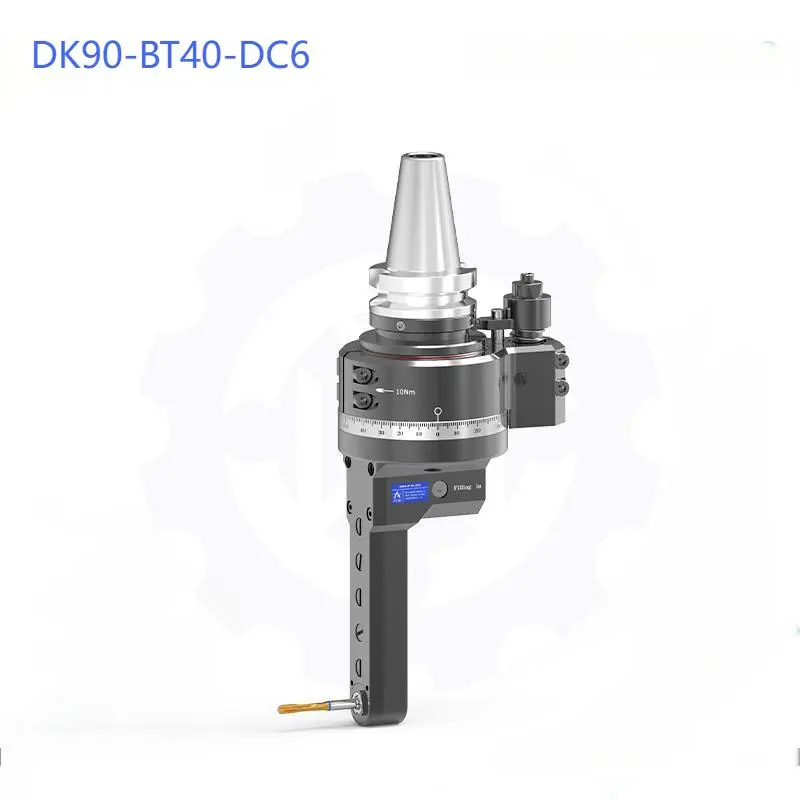
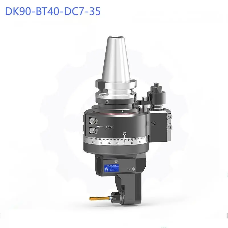
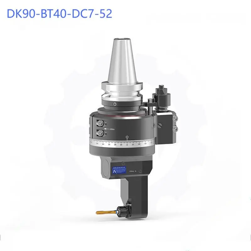
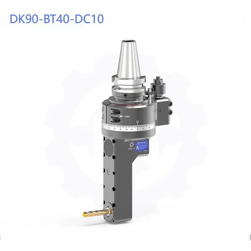
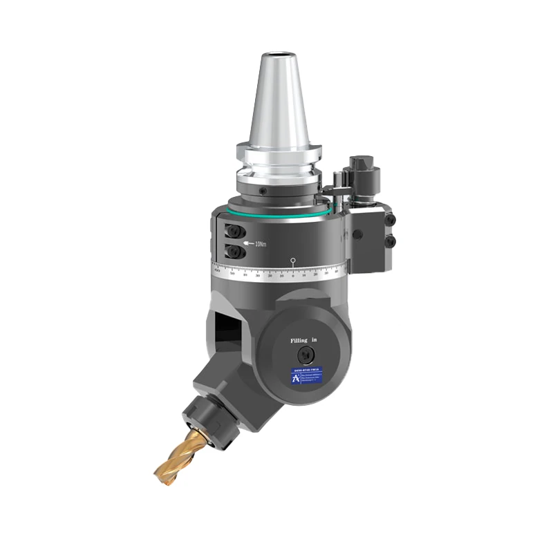
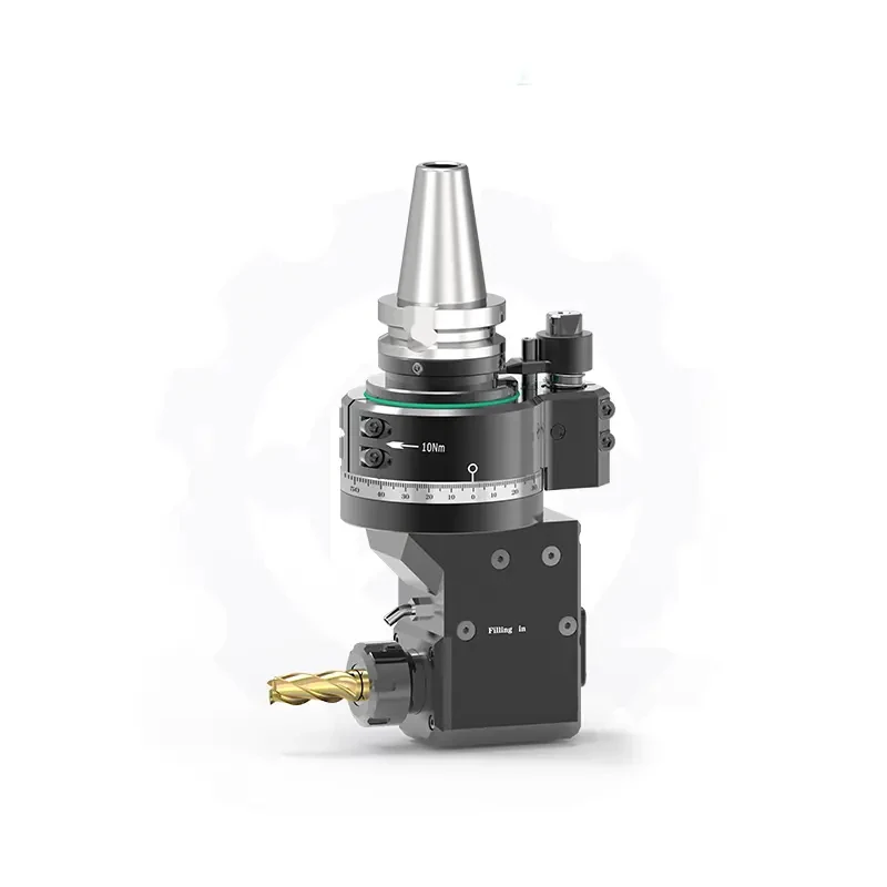
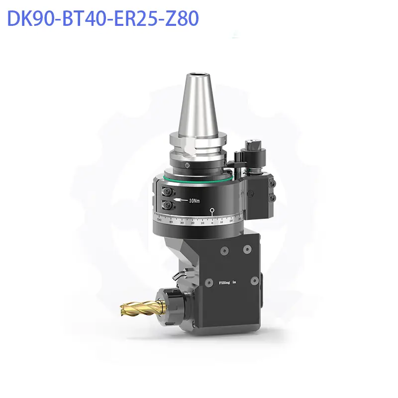
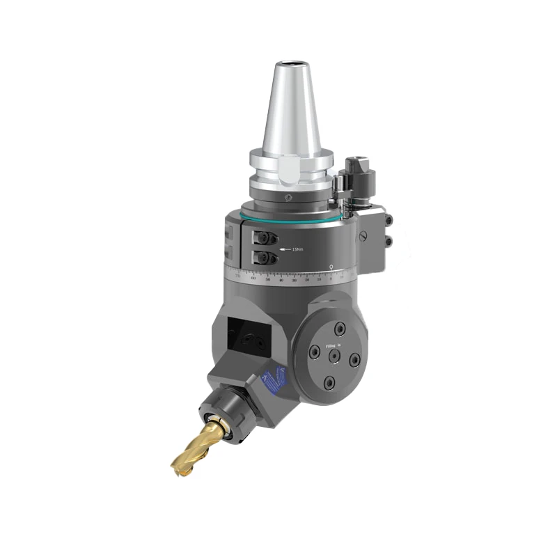
The DK90-BT40 DC Series (including DC5M, DC6, DC7, DC8, and DC10) is a high-precision, ultra-slim 90-degree right angle head engineered specifically for narrow cavity side milling, internal slotting, and deep bore thread processing on BT40 vertical machining centers (VMC). By utilizing a pull-back DC double-chuck collet mechanism instead of standard external collet nuts, this series reduces the cutter nose swing diameter down to D35 mm, enabling deep-pocket access where standard ER angle heads collide.


Featuring rigid monoblock housing construction and high-torque Gleason bevel gears, the DK90-BT40 DC series transmits up to 23.0 Nm of cutting torque. It is suitable for finishing internal keyways, mold slider tracks, and hydraulic valve chambers in confined workpieces.


Key Technical Features and Material Standards

  • Ultra-Compact DC Pull-Back Collet System: Employs an internal draw-in DC collet mechanism that eliminates wide external clamping nuts. This slims the maximum head swing diameter down to D35 mm (DC6) and D40 mm (DC5M), providing clearance in narrow spaces.
  • High-Rigidity Casing: Cast from high-strength structural material and treated with stress-relief heat treatment. The monoblock casting absorbs cutting vibration during deep-reach side milling while maintaining thermal stability under continuous operation.
  • Gleason Ground Spiral Bevel Gears: Manufactured from 20CrMnTi Alloy Steel, gas-carburized and quenched to HRC 58-62, and ground to ISO Grade 4 precision on Gleason CNC grinders. Ensures transmission backlash ≤ 15 arcmin and running noise ≤ 70 dB under full operational load.
  • P4 Class Preloaded Spindle Bearings: Supported by preloaded, high-precision P4 grade angular contact ball bearings (NSK/FAG), maintaining spindle nose runout ≤ 0.005 mm and rotational concentricity up to 6,000 RPM.

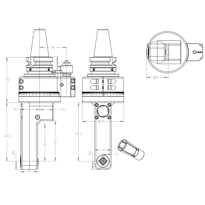
2D/3D Technical Drawings and CAD Download Center

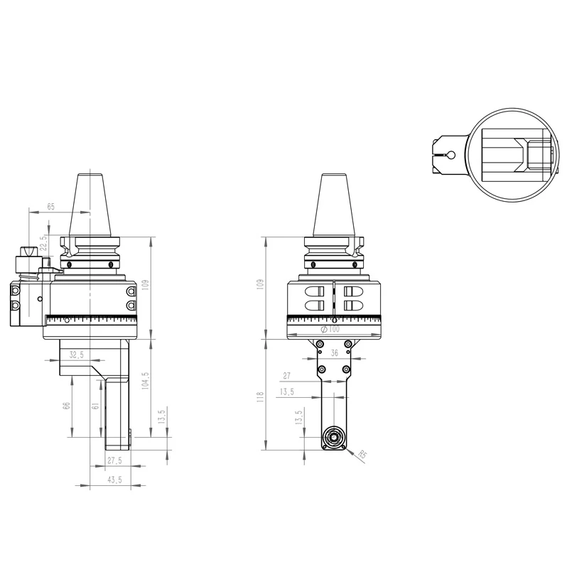
BT40-DC6-66

slim 90° right angle head (dk90 bt40 dc collet series)

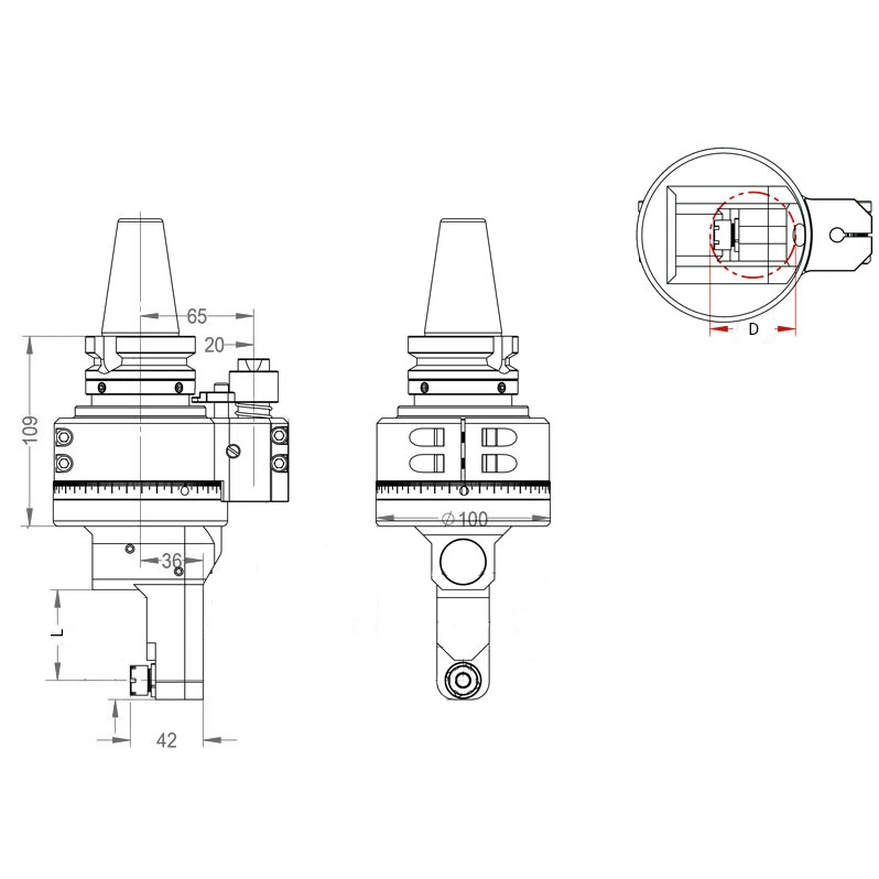
BT40-DC7

slim 90° right angle head (dk90 bt40 dc collet series)

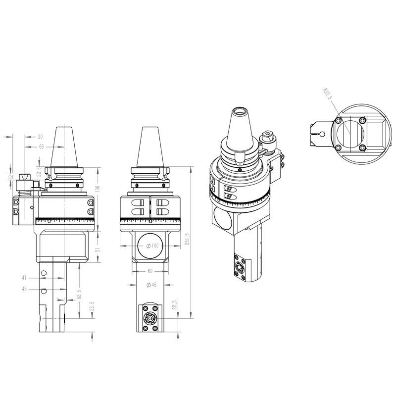
BT40-DC8

slim 90° right angle head (dk90 bt40 dc collet series)

BT40-DC10

slim 90° right angle head (dk90 bt40 dc collet series)

Technical Specifications

ModelInput ShankSpindle OutputGage Length (L)Max. SpeedGear RatioPassing Dia. (D)Clamping RangeTapping CapacityMax. TorqueNet WeightStock Status
DK90-BT40-DC5M-50BT40DC5M50 mm6,000 RPM1:1D40 mmØ1.0 – Ø5.0 mmM3 – M45.6 Nm5.000 kgAlways in Stock
DK90-BT40-DC6-66BT40DC666 mm6,000 RPM1:1D35 mmØ1.0 – Ø6.0 mmThread Milling10.8 Nm4.891 kgAlways in Stock
DK90-BT40-DC7-18.5BT40DC718.5 mm6,000 RPM1:1D50 mmØ1.0 – Ø7.0 mmThread Milling10.8 Nm4.556 kgAlways in Stock
DK90-BT40-DC7-35BT40DC735 mm6,000 RPM1:1D50 mmØ1.0 – Ø7.0 mmThread Milling10.8 Nm5.196 kgAlways in Stock
DK90-BT40-DC7-52BT40DC752 mm6,000 RPM1:1D50 mmØ1.0 – Ø7.0 mmThread Milling10.8 Nm5.310 kgAlways in Stock
DK90-BT40-DC8-45BT40DC845 mm6,000 RPM1:1D45 mmØ4.0 – Ø10.0 mmM5 – M1023.0 Nm6.500 kgAlways in Stock
DK90-BT40-DC10-140.5BT40DC10140.5 mm6,000 RPM1:1D51 mmØ4.0 – Ø10.0 mmM5 – M1023.0 Nm6.500 kgAlways in Stock

Quality Assurance and Testing Standards

Before dispatch, every DK90-BT40 DC series angle head undergoes a 100% Quality Inspection Protocol:

  • Static and Dynamic Runout Test: Spindle taper and DC collet cone runout are measured with a high-precision dial indicator, held to ≤ 0.005 mm at the spindle nose and ≤ 0.015 mm at 4D distance.
  • 60-Minute Continuous Run-In: Tested continuously at rated operating speed for 60 minutes. Housing temperature rise must remain ≤ 25°C above ambient temperature.
  • Anti-Backlash Calibration: Verified with angular encoders to confirm transmission backlash remains ≤ 15 arcminutes under rated load.

Target Industries and Industrial Applications

  • Precision Mold and Die Cavities: Machining internal side-walls, slider tracks, and narrow ejector pin channels in hardened steel mold bases where standard nuts collide.
  • Hydraulic and Pneumatic Valve Blocks: Finishing internal ring grooves, seal seats, and cross-drilled passages inside compact manifold enclosures.
  • Automotive Transmission and Engine Housings: Side drilling, slotting, and thread milling inside deep internal bores of cast aluminum and iron housings.

CNC Machine Compatibility

Optimized for medium-to-large Vertical Machining Centers (VMC) and Horizontal Machining Centers (HMC). Compatible spindle interfaces include:

  • Spindle Standards: BT40 / BBT40 (Face & Taper double contact) / SK40 / HSK63A.
  • Typical Machine Brands: Compatible with Haas, Mazak, Okuma, Doosan / DN Solutions, Makino, and Hurco machine tools.

B2B Industrial Packing and Shipping Standards

  • Anti-Rust Protection: Coated with heavy-duty anti-rust oil and vacuum-sealed in a high-barrier VCI (Vapor Corrosion Inhibitor) bag accompanied by industrial desiccant packs.
  • Shock Absorption: Cradled inside custom-contoured, high-density polyurethane protective foam inserts to isolate the BT40 taper and long housing from transport shock.
  • Export Outer Casing: Each unit is securely crated in an ISPM 15-compliant, Fumigation-Free Plywood Wooden Case equipped with quick-locking metal clasps.
  • HS Code: 8466.10.10.00 or 8466.30.00.90.
  • Lead Time: Standard models are shipped within 5-7 working days. Custom positioning blocks (G-distance) are completed and shipped within 15-20 working days.
  • Shipment Ports: Shanghai / Ningbo / Tianjin Port, China.
  • Incoterms Supported: FOB, CIF, EXW, FCA, DDU, DDP.
  • Express Delivery: Shipped via international air couriers (DHL, FedEx, UPS) with delivery to Europe and North America within 3-5 business days.

Technical Setup and Stop Block Alignment Guide

codeText

       ┌──────────────────────────────────────┐
       │     MACHINE TOOL SPINDLE FACE        │
       └──────────────────┬───────────────────┘
                          │ (Spindle Centerline)
                          │ 
                          ▼◄──────  G  ──────►[STOP BLOCK]
                       ┌─────┐                    │
                       │Taper│                    │ (Locking Bore)
                       └─────┘                    ▼
                          │               ┌───────────────┐
                     ┌────┴────┐          │ Positioning   │
                     │  Body   ├──────────┤ Pin (D18/D20) │
                     │  Casing │          └───────────────┘
                     └─────────┘
  1. Stop Block Mounting: Securely bolt the dedicated stop block (retaining block) to the front face of the VMC machine spindle.
  2. Verify Center Distance (G-Dimension): Confirm that the center-to-center distance between the machine spindle and positioning pin socket matches your ordered G-Distance (commonly 65mm, 80mm, or 110mm).
  3. Indicate Side Runout: Chuck a ground test arbor into the DC collet. Sweeping a dial indicator along the arbor horizontally, adjust the stop block’s locking bolts until parallelism is aligned within 0.015 mm per 100mm.
  4. Confirm ATC Clearances: Run a manual tool changer (ATC) test cycle at low speed to verify the automatic arm smoothly grabs, seats, and releases the BT40 taper without physical interference.

Technical FAQ

A: The DC collet system uses an internal draw-in mechanism rather than a large external clamping nut. This design dramatically reduces the outer passing diameter (down to D35 mm on DC6 models compared to D100 mm on ER16 models), enabling side milling inside narrow slots and internal bores without tool body interference.

A: The short-projection DC7 models are designed for maximum rigidity in shallow cavities. By keeping the Gage Length (L) down to 18.5 mm or 35 mm, tool overhang leverage is minimized, allowing chatter-free side milling and thread milling at full torque (10.8 Nm).

A: Yes. DC collets are clamped using a dedicated front-end hex or spanner key that engages the collet mechanism directly. Each DK90-BT40 DC series angle head ships with the required clamping wrench.

You May Also Like