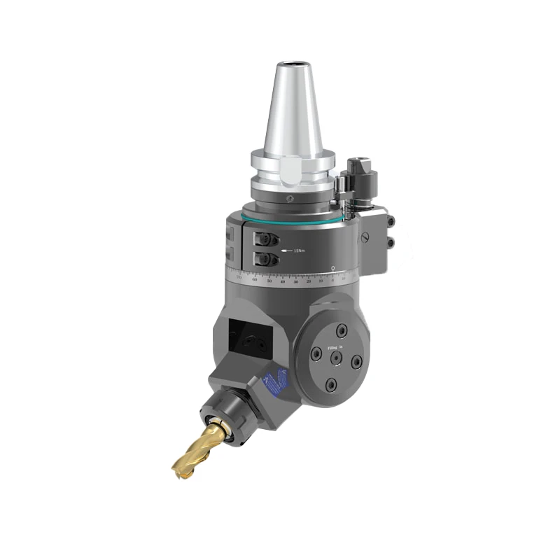
Universal Swivel Milling Angle Head (DK90-BT50 YW & WXER Series)
The DK90-BT50 YW & WXER Series (comprising DK90-BT50-YW16, DK90-BT50-YW20, and DK90-BT50-WXER32) is a heavy-duty, adjustable universal swivel…
View Details
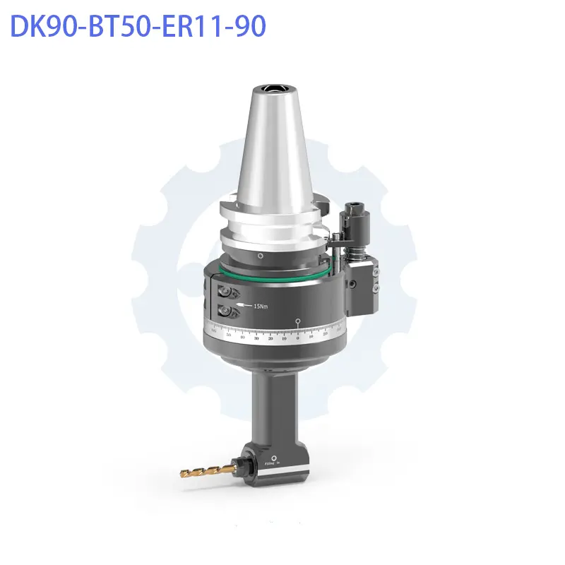
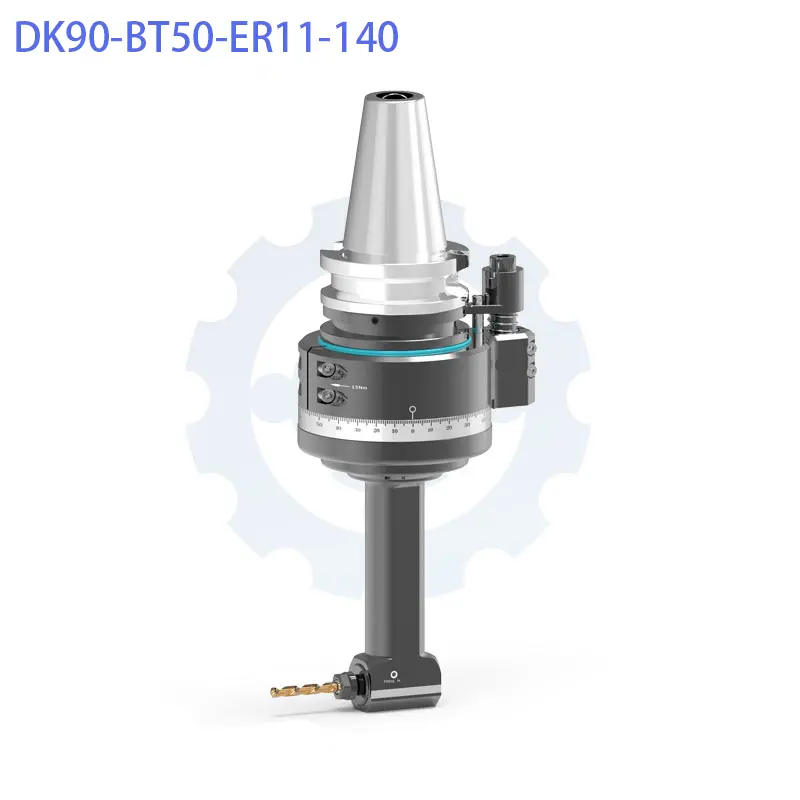
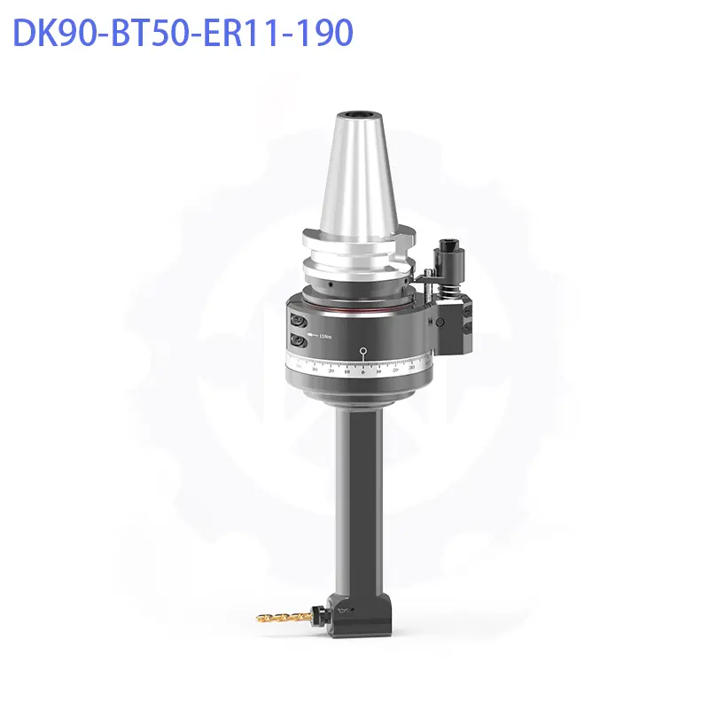
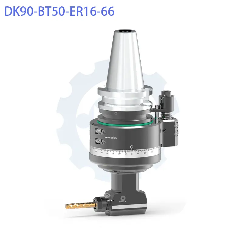
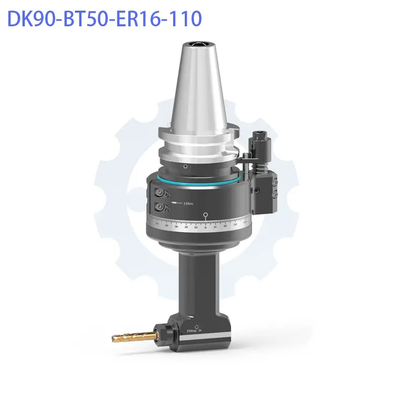
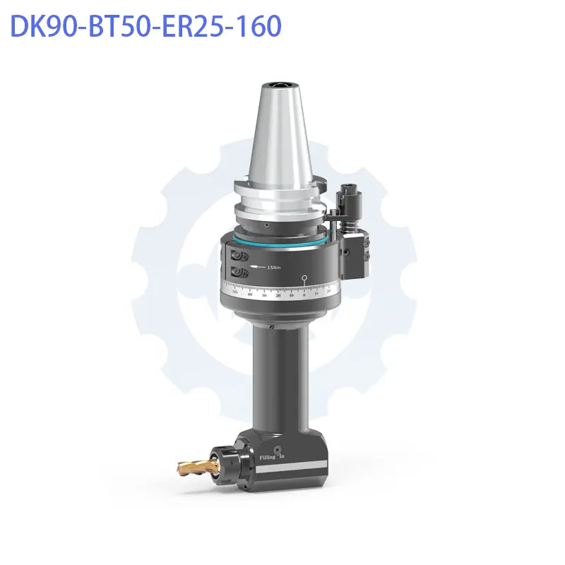
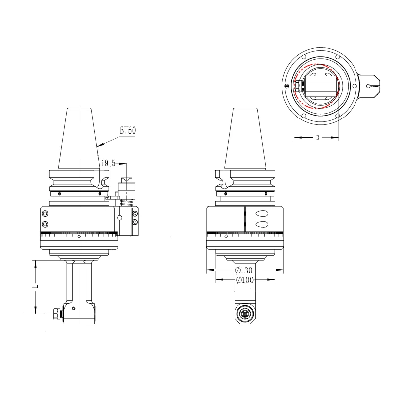
| Model | Input Shank | Spindle Output | Gage Length (L) | Max. Speed | Gear Ratio | Passing Dia. (D) | Clamping Range | Tapping Capacity | Max. Torque | Net Weight | Stock Status |
| DK90-BT50-ER11-90 | BT50 | ER11 | 90 mm | 8,000 RPM | 1:1 | D75 mm | Ø1.0 – Ø7.0 mm | M5 – M6 | 8.8 Nm | 11.446 kg | Always in Stock |
| DK90-BT50-ER11-140 | BT50 | ER11 | 140 mm | 8,000 RPM | 1:1 | D75 mm | Ø1.0 – Ø7.0 mm | M5 – M6 | 8.8 Nm | 11.715 kg | Always in Stock |
| DK90-BT50-ER11-190 | BT50 | ER11 | 190 mm | 8,000 RPM | 1:1 | D75 mm | Ø1.0 – Ø7.0 mm | M5 – M6 | 8.8 Nm | 12.190 kg | Always in Stock |
| DK90-BT50-ER16-66 | BT50 | ER16 | 66 mm | 8,000 RPM | 1:1 | D100 mm | Ø1.0 – Ø10.0 mm | M5 – M8 | 18.0 Nm | 11.447 kg | Always in Stock |
| DK90-BT50-ER16-110 | BT50 | ER16 | 110 mm | 8,000 RPM | 1:1 | D100 mm | Ø1.0 – Ø10.0 mm | M5 – M8 | 18.0 Nm | 5.391 kg | Always in Stock |
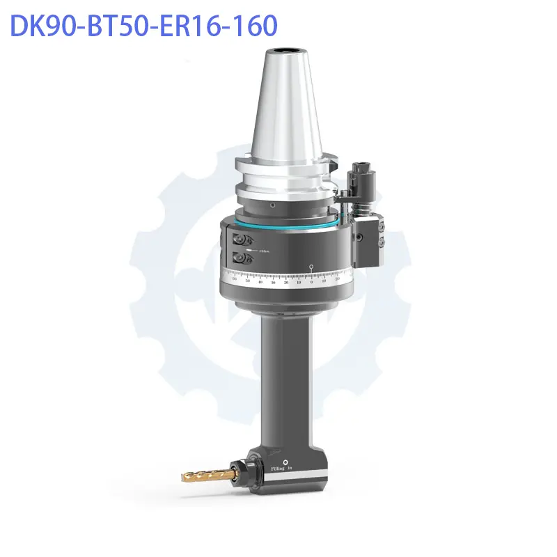
| DK90-BT50-ER16-160 | BT50 | ER16 | 160 mm | 8,000 RPM | 1:1 | D100 mm | Ø1.0 – Ø10.0 mm | M5 – M8 | 18.0 Nm | 5.823 kg | Always in Stock |
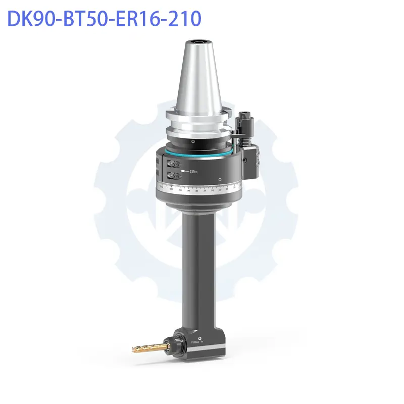
| DK90-BT50-ER16-210 | BT50 | ER16 | 210 mm | 8,000 RPM | 1:1 | D100 mm | Ø1.0 – Ø10.0 mm | M5 – M8 | 18.0 Nm | 12.870 kg | Always in Stock |
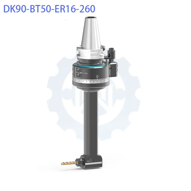
| DK90-BT50-ER16-260 | BT50 | ER16 | 260 mm | 8,000 RPM | 1:1 | D101 mm | Ø1.0 – Ø11.0 mm | M5 – M9 | 18.0 Nm | 13.447 kg | Always in Stock |
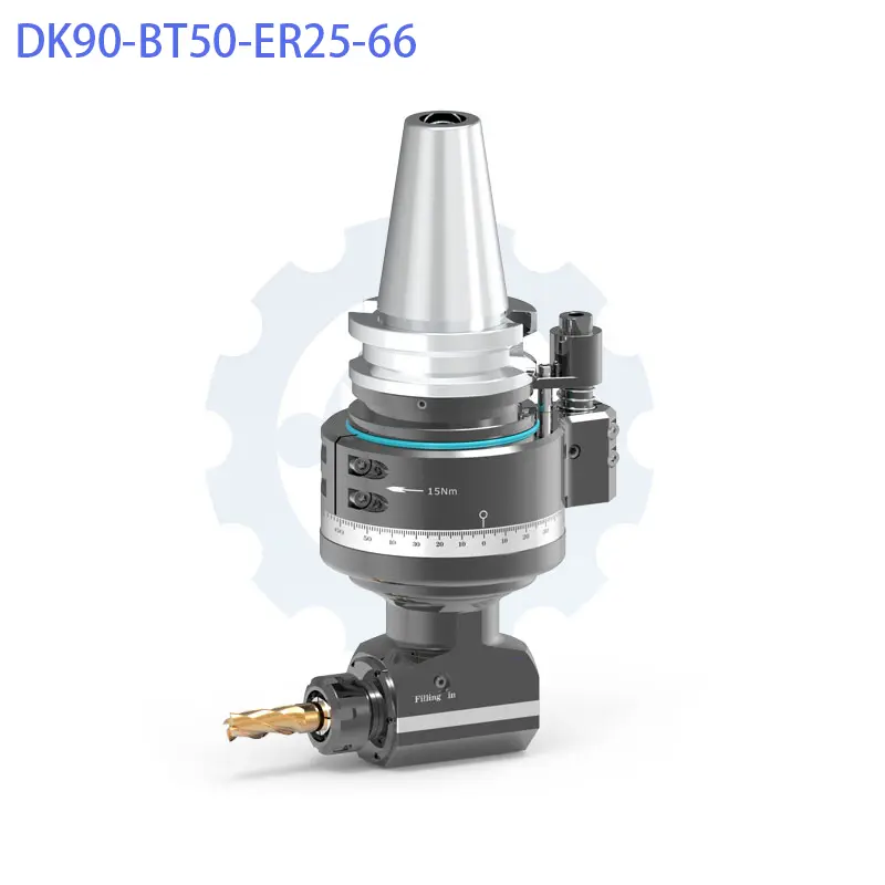
| DK90-BT50-ER25-66 | BT50 | ER25 | 66 mm | 6,800 RPM | 1:1 | D130 mm | Ø1.0 – Ø16.0 mm | M6 – M14 | 46.0 Nm | 12.523 kg | Always in Stock |
| DK90-BT50-ER25-110 | BT50 | ER25 | 110 mm | 6,800 RPM | 1:1 | D130 mm | Ø1.0 – Ø16.0 mm | M6 – M14 | 46.0 Nm | 13.081 kg | Always in Stock |
| DK90-BT50-ER25-160 | BT50 | ER25 | 160 mm | 6,800 RPM | 1:1 | D130 mm | Ø1.0 – Ø16.0 mm | M6 – M14 | 46.0 Nm | 13.706 kg | Always in Stock |
| DK90-BT50-ER25-210 | BT50 | ER25 | 210 mm | 6,800 RPM | 1:1 | D130 mm | Ø1.0 – Ø16.0 mm | M6 – M14 | 46.0 Nm | 14.932 kg | Always in Stock |
| DK90-BT50-ER25-250 | BT50 | ER25 | 250 mm | 6,800 RPM | 1:1 | D130 mm | Ø1.0 – Ø16.0 mm | M6 – M14 | 46.0 Nm | 16.403 kg | Always in Stock |
| DK90-BT50-ER25-300 | BT50 | ER25 | 300 mm | 6,800 RPM | 1:1 | D130 mm | Ø1.0 – Ø16.0 mm | M6 – M14 | 46.0 Nm | 17.454 kg | Always in Stock |
| DK90-BT50-ER32-80 | BT50 | ER32 | 80 mm | 5,000 RPM | 1:1 | D155 mm | Ø1.0 – Ø20.0 mm | M6 – M16 | 65.0 Nm | 12.670 kg | Always in Stock |
| DK90-BT50-ER32-125 | BT50 | ER32 | 125 mm | 5,000 RPM | 1:1 | D155 mm | Ø1.0 – Ø20.0 mm | M6 – M16 | 65.0 Nm | 12.397 kg | Always in Stock |
| DK90-BT50-ER32-170 | BT50 | ER32 | 170 mm | 5,000 RPM | 1:1 | D155 mm | Ø1.0 – Ø20.0 mm | M6 – M16 | 65.0 Nm | 14.500 kg | Always in Stock |
| DK90-BT50-ER32-190 | BT50 | ER32 | 190 mm | 5,000 RPM | 1:1 | D178 mm | Ø1.0 – Ø20.0 mm | M6 – M16 | 65.0 Nm | 16.890 kg | Always in Stock |
| DK90-BT50-ER40-80 | BT50 | ER40 | 80 mm | 4,000 RPM | 1:1 | D155 mm | Ø1.0 – Ø26.0 mm | M6 – M18 | 65.0 Nm | 15.500 kg | Always in Stock |
Before packaging, every DK90-BT50 ER series angle head undergoes a 100% Quality Inspection Protocol:
Designed for large Vertical Machining Centers (VMC), Horizontal Machining Centers (HMC), and Gantry Milling Machines. Compatible spindle shanks include:
codeText
       ┌──────────────────────────────────────┐
       │     MACHINE TOOL SPINDLE FACE        │
       └──────────────────┬───────────────────┘
                          │ (Spindle Centerline)
                          │
                          ▼◄──────  G  ──────►[STOP BLOCK]
                       ┌─────┐                    │
                       │Taper│                    │ (Locking Bore)
                       └─────┘                    ▼
                          │               ┌───────────────┐
                     ┌────┴────┐          │ Positioning   │
                     │  Body   ├──────────┤ Pin (D18/D20) │
                     │  Casing │          └───────────────┘
└─────────┘A: Maximum rotational speed is constrained by the pitch diameter and mass of the larger output spindle assembly. The ER40 output spindle accommodates tools up to Ø26.0 mm and transmits up to 65 Nm of torque. Capping the continuous operating speed at 4,000 RPM prevents excessive centrifugal force, manages bearing heat generation, and ensures long service life under heavy load.
A: Yes. The combination of the heavy QT500-7 ductile iron body, 20CrMnTi Gleason ground gears, and P4 angular contact bearings provides high static and dynamic rigidity. It is suitable for face milling and shoulder milling on medium carbon steels, die steels, and alloy steels using carbide end mills within recommended torque limits (up to 65 Nm).
A: Yes. Because horizontal machining centers often feature different spindle nose configurations and automatic tool changer door clearances compared to vertical machines, a custom stop block is required. Please submit our Technical Worksheet with your spindle face dimensions to receive a custom-machined stop block.
The DK90-BT50 YW & WXER Series (comprising DK90-BT50-YW16, DK90-BT50-YW20, and DK90-BT50-WXER32) is a heavy-duty, adjustable universal swivel…
View Details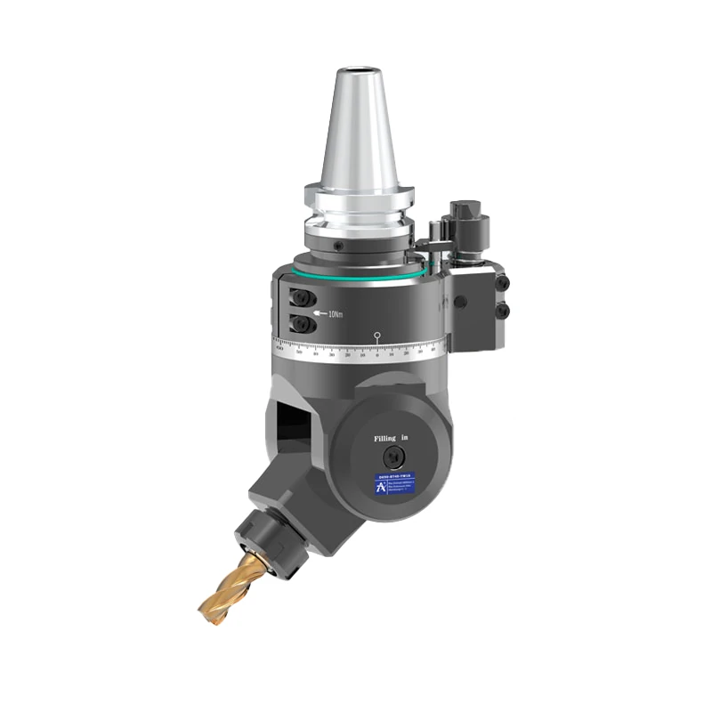
The DK90-BT40 W13 & YW16 Series comprises high-rigidity 90-degree milling angle heads engineered for medium-to-heavy side milling,…
View Details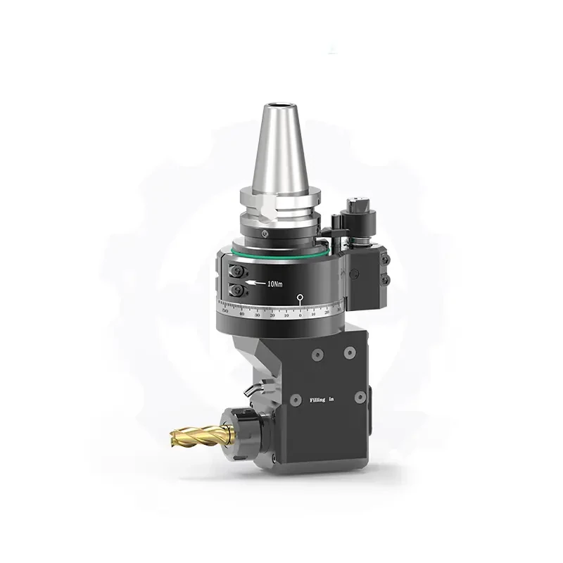
The DK90-BT50-ER25-Z80 is a heavy-duty, internal coolant-through-spindle (CTS) 90-degree right angle head engineered for high-efficiency side drilling,…
View Details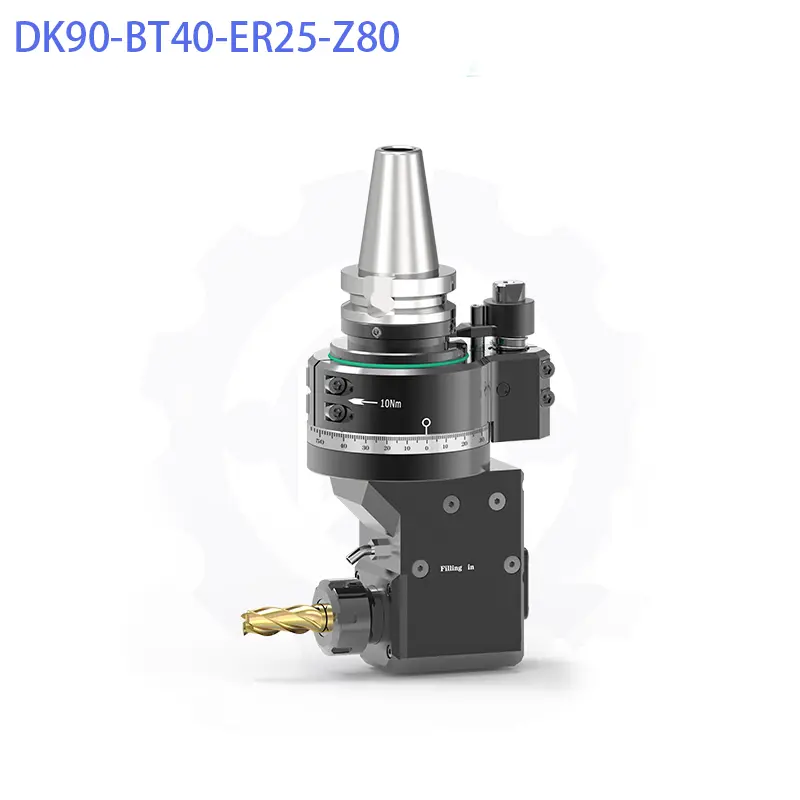
The DK90-BT40-ER25-Z80 is a heavy-duty, internal coolant-through-spindle (CTS) 90-degree right angle head engineered for high-efficiency side drilling,…
View Details